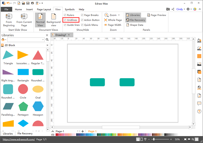
Floor Plan Symbols Gridlines

How To Create Column Grid Of The Building Autocad Architecture Blog Grid Architecture Autocad Create Floor Plan

Grid Line An Overview Sciencedirect Topics
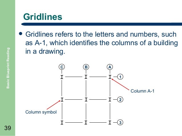
Basic Blueprint Reading
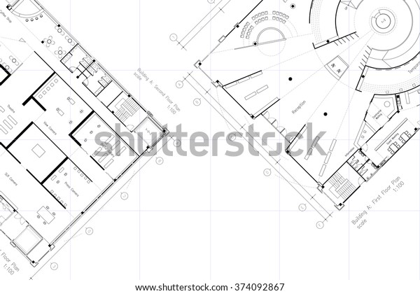
Architectural Layout Floor Plan Grid Lines Stock Illustration 374092867
Building In Modelling Architecture Life Since 2015

How To Get Missing Revit Grid Or Level Lines Back Micrographics
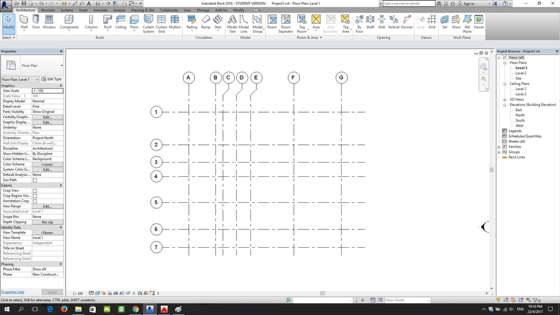
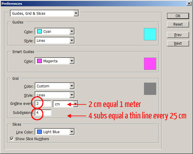
A word of caution the figure a drawing was mocked up just for training purposes.
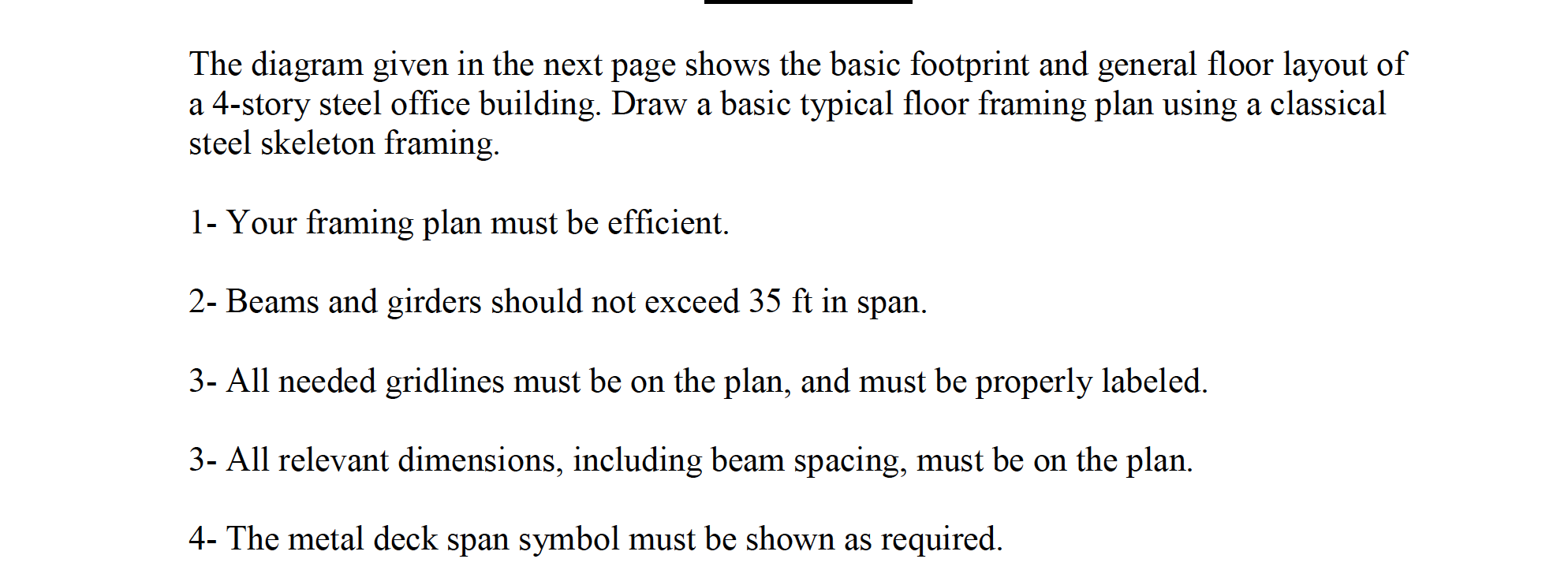
Floor plan symbols gridlines. For uniformity and clarity of understanding standard abbreviations and symbols have been adopted by the department. An architectural drawing provided with shading for the accentuate features wall dashed lines in architectural drawings. Exterior walls of a building are dimensioned outside the floor plan. For example columns are usually assigned a grid number and referenced to the column centerline for dimensioning purposes figure 6 25.
Gridlines are the identification marks of a floor plan. That finished the floor plans for now. Dimensioning on a floor plan usually requires two or three continuous dimension lines to locate exterior walls wall jogs interior walls windows doors and other elements as shown in figure 6 36. Also numerous symbols are used on plan sheets to represent existing topography property lines and objects to be built.
Often the ground ffl will be nominated at 0 00 metres high with all other. That would mean that all the detail cuts section cuts and interior elevations would be on pages higher in the a 2. When you create a floor plan on your own you can decorate it with different symbols from our extensive symbol libraries containing over 600 2d floor plan symbols just drag floor plan symbols that you want and drop them onto the canvas. The legend on a 101 above notes the symbols for slab on grade concrete typ.
To represent and show those features that are not visible or have no relationship with the view of the plan dashed lines are used in the architectural drawings. That determines the identity of one particular position of a. A number of specialized symbols are used on the floor plan. And letters 1 to 2 etc along the horizontal direction.
The legend summarizes what all symbols textures and icons mean. 1 24 page 1 73 of the construction manual. The outermost dimension line is the overall building dimension. Series not lower as the examples above show.
Typically the floor plan will be page a 2 a 2 1 or a 2 3. Use your plan to measure the location of each corner of the building including offsets. Foundation footprint floor drain elevation marks and sand gravel. The list below is taken from fig.
These are usually letters from a to z etc along the vertical direction. Next it s crucial to review the drawing s legend. And more importantly use the easy scale tools to. Finished floor level tags.
The legend should be. Align and arrange walls fixtures and outlets in the suitable places. Sea level or another nominated level. Your site plan or architectural floor plan should have a bench mark a bench mark refers to some item such as a manhole lid or survey waypoint with a known elevation elevation or a height above existing grade as a starting point.
Gridlines are drawn in accordance with land survey.
Floor Plan Designing Buildings Wiki

Reading Drawings Josh Brincko
Ceiling And Floor Perspective Grid Lines Vector Image

Grid Line With Gap In Revit Youtube

Grids Revit Products 2019 Autodesk Knowledge Network
Https Www Gsa Gov Cdnstatic Did Review Guide Final Pdf

How To Re Size Grid Head In Revit Architecture Youtube

Work In Progress Bim Wip

2 Nd Floor Plan And Gridlines For Transfer Beam And Column Locations Download Scientific Diagram
Hiding A Linked Model S Levels And Grids In Revit Best Cad Tips

Datum Elements Learning Revit Online
Tutorial Rotate And Scale A Scanned Floor Plan In Adobe Photoshop Plan Symbols